  Read about the remake of the classic Udat case.
|
Many of you have read that servos were used to lift the wings in the Y2k-bug,
however it didn't explain how they were controlled. This guide will explain how it was done and also how you can add similar features to your own case.
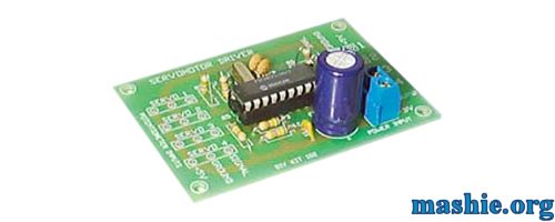
The main component for this guide is the Four Servo Motor Driver.
This is how the manufacturer explains the functionality of their kit:
Servo motors are used in radio-controlled models (cars, planes), robotics, theme park special effects, test equipment, industrial automation. At the hobbyist end of the market they are small, compact and relatively inexpensive at around $US20. The motors themselves are black boxes which contain a motor, gearbox and decoder electronics. Three wires go into the box; 5V, ground and signal. A short shaft comes out of the motor which usually has a circular interface plate attached to it. Most servos will rotate through about 100 degrees in less than a second according to signal input. This kit will control up to 4 servo motors simultaneously. All the work controlling the servos is done in the preprogrammed PIC micro-controller (uC). As such the kit provides a textbook example of how a uC can replace a handful of IC's and other glue chips. The input signals are between 0 - 5V delivered by connecting up the potentiometers as voltage dividers. Inside the PIC and AD converter (multiplexed when there is more than one input signal) changes the voltage signal into the Pulse Code Modulation system used by servo motors. This signal is a 5V pulse between 1 and 2 msec long repeated 50 times per second. That is, a 20msec frame rate. The width of the pulse determines the position of the server. Most servos will move to the center of their travel when they receive a 1.5msec pulse. One extreme of motion generally equates to a pulse width of 1.0msec; the other extreme to 2.0msec with a smooth variation throughout the range, and neutral at 1.5msec. The period between the pulses is used to synchronize the receiver. Servos are closed loop devices. They are constantly comparing their position (proportional to the pulse width) to their actual position (proportional to the signal voltage input). If there is a difference between the two, the servos electronics will turn the motor to adjust the difference error. This also means that servos will resist forces which try to change their position. When a servo is unpowered or not receiving positioning pulses the output shaft can be easily turned by hand. So in short you use one potentiometer for each servo, when you turn the potentiometer the servo will move the same distance. 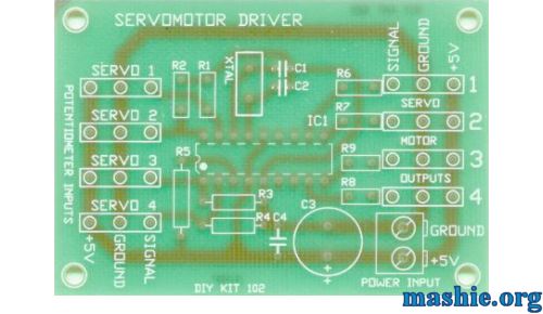 As you can see the layout is really simple, in the middle goes the PIC processor and a few other
bits and pieces included in the kit. To the left you connect the potentiometers and
to the right you connect the servos. At the bottom right you have the connector for +5V and GND to
power it all.
So by just assembling the kit you have a servo that follows the motion of a potentiometer, kind of fun but not very useful for a case mod. If you plan to have a panel flip out or a baybus to open up you need a servo that moves between two predefined positions.  The easiest solution can be seen in the picture above: two potentiometers and a switch. The switch
select which potentiometer output that will be sent to the controller and then make the servo move
to the position set.
Stuff moving by the flick of a switch is nice, stuff moving automatically when the computer is booted up is nicer...  This solution is slightly more complicated than the previous approach, first you need to ensure
that the servo can move back to the start position when the computer is shut down. To do this we need
a +5V line that is always on even when the computer itself isn't running. The easiest way is to tap
in to the +5V Stand By (+5VSB) line from the PSU. The +5VSB is part of the ATX standard to keep
wake-on-call devices powered on and modern PSUs should be able to supply around 2A depending on
brand. The wire with the +5VSB line is easy to find due to the fact it is the only violet wire in the
cable harness. Unfortunately this cable still needs to be connected to the motherboard so don't cut
it off just make a Y connection and it will work just fine.
Now when we have a reliable power source, we need to get the controller board to detect if the computer has been turned on or off. By using a 5V relay and a protection diode connected to the normal 5V line from a Molex connector the relay will direct the signal from one potentiometer when the computer is on and the other when it is off. So the full procedure will be, computer is plugged it to the wall, the +5VSB lines go active turning on the controller. The relay is off due to the lack of normal 5V signal so the input from the left potentiometer is sent to the controller and moving the servo to the configured OFF position. When you boot up the computer, the 5V line goes active switching the relay to the other position sending the input from the right relay to the controller. The servo moves to the ON position. Later when the computer is shut down the relay will switch back due to lack of 5V and the servo return to the OFF position. I have located a couple of places around the globe that sells this kit so hopefully you can find one near your region: Carl's Electronics (USA) Q Kits (Canada) Quasar Electronics (UK) There you go, a simple hack with a great potential in the world of case mods. The only drawback is that you can't regulate the speed of the servos so whatever the servos move, will move quite fast.
|
||||||
| All trademarks used are properties of their respective owners. All rights reserved Copyright © 2002 - 2020 by Mashie Design |


